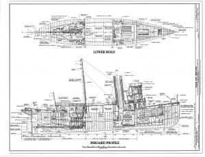
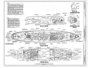
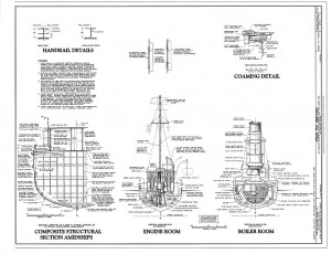
Click on image for medium-resolution plans; High-resolution plan links at bottom of page
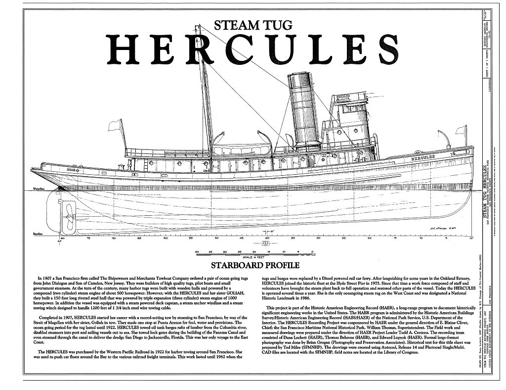
In 1907 the San Francisco firm The Shipowners and Merchants Towboat Company ordered two ocean-going tugboats from John Dialogue and Son of Camden, New Jersey, builders of tugs, pilot boats, and small steamers. At the turn of the century many harbor tugs were built with wooden hulls and powered by a compound two-cylinder steam engine of about 500 horespower. Hercules and her sister Goliah instead were built with 150 foot riveted steel hulls and thriple expansion three-cylinder 1000 horsepower steam engines. They were also given steam powered deck capstans, steam anchor windlasses, and steam towing winches designed for 1,200 feet of 1.75 inch steel towing cable.
Hercules started her career by towing Goliah through the Strait of Magellan to reach San Francisco, with just one stop for fuel, water, and provisions. Until 1922 Hercules towed barges and rafts of lumber from the Columbia River, as well as bringing disabled steamers into port and sailing vessels out to sea. During the building of the Panama Canal she towed gates for the locks, and steamed through the canal to deliver a dredge to Florida.
In 1922 the Western Pacific Railroad purchased Hercules for harbor towing. Until 1962 she delivered car floats to the railroad freight terminals around San Francisco Bay. After the steam tugs were replaced by a diesel-powered car ferry, Hercules languished in the Oakland Estuary until moved to they Hyde Street Pier in 1975. A group of museum staff and volunteers have restored her steam engine, allowing Hercules to be operated several times a year, keeping the heritage of steam power alive.
The only ocean-going steam tug on the West Coast, Hercules was designated a National Historic Landmark in 1986. She was was documented as part of the Historic American Engineering Record, a program of the National Park Service. The photos and drawings from that survey are kept by the Library of Congress.
High-Resolution Plan Links
3. Deck Plan
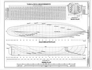
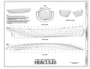
5. Lines Plan
[…] Two of our favorites are the U.S. Coast Guard Cutter White Sumac, and the Steam Tug Hercules. […]
[…] Free Ship Plans offer Ship Model builder loads of detail […]
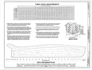
A gentleman named Lee asked about the what the measurements in the Table of Hull Measurements mean. I was unable to reply via email, so I’ll post the body of the email here:
Lee,
Thanks for visiting the website. I’ve always thought the best way to visualize a ship plan is to think of it as various ways to cut a loaf of bread. The stations in the Body Plan are sections of the hull that would be like normal slices of bread. The waterlines (W.L.) in the Half Breadth Plan are as if you sliced the bread horizontally. The Buttocks in the Sheer Plan are as if you sliced the bread vertically, but along the long dimension of the loaf,
The Table of Hull Measurements (sometimes called the Table of Offsets) for the Stations gives you the height and width measurements of each particular station at a particular point. On the Heights portion of the table, those heights are measured from the 0’0″ waterline. The Sheer is the the uppermost point, where the deck and hull meet. The Rabbet is the point where the hull meets the keel. The Buttocks are all the vertical slices in between. On the Widths part of the table, all measurements are from the centerline of the ship out to the various waterlines shown on the Half-breadth Plan. The Diagonals are imaginary lines drawn at a 45 degree from the centerline toward the baseline (0’0″ waterline) and ending where a particular waterline meets the widest point of the vessel. These lines are used along the most curved part of the hull to give measurement points between the heights and half-breadths to ensure a “fair” curve. All of these measurements are double-checks to the lines on the Body Plan, and are used by the shipwright to lay out the full size frame.
I apologize if you knew all that, but it’s important in understanding the measurements you asked about.
The convention for those measurements is Feet-Inches-Fractions of an Inch (the smallest fraction important in that size ship, normally eighths. On small boats it might be sixteenths. A quick way to figure out what it is: look for the highest number in that last measurements. If it’s less than eight, it’s almost certainly eighths. If it’s higher than eighths, the measurement is in sixteenths).
So then, to make a short story long, the height of section one from the 0’0″ waterline to the sheer is 20 feet, two inches, and one-eighth of an inch.
[…] Free Ship Plans offer Ship Model builder loads of detail […]
[…] Steam Tug Hercules […]